Coding line integration and data control
Integration guide

Coding line integration and data control

Plan the trigger, speed reference, message data, verification and failure response that connect a coding machine to the production line.

Begin with a signal and data schedule

List every physical and digital exchange before controls work starts. This avoids assuming that a printer interface automatically provides a complete line integration.

The physical product path determines the timing architecture. A stable carton or bottle on a constant-speed conveyor may need a product sensor and a fixed trigger delay. A variable-speed web or conveyor can require an encoder so the printer follows distance rather than time. The selected printer, host machine and code-position tolerance determine the final method.

Define all signals that are required or available: product present, print trigger, encoder pulses, job loaded, printer ready, warning, fault, low consumable, print complete, inspection result and reject command. Not every model provides every signal, so the final I/O schedule must be checked against the selected equipment.

For data, identify the source of product code, date, batch, serial number, barcode and 2D fields. A USB file, serial connection or TCP/IP socket is not a complete specification. Record the protocol, field names, format, character set, acknowledgements, update timing and response to invalid or missing data.

ERP or MES integration usually needs an intermediate controls or software layer that manages jobs and communicates with the printer. Confirm who supplies and supports that layer, how users authenticate, how templates are version-controlled and what happens if the business system or network is unavailable.

The operator interface should make the active product and message obvious. Editing rights, job-selection rules and first-off confirmation should reflect the process risk. Automated data transfer reduces repeated typing but does not remove the need to confirm the correct physical material and product are on the line.
Typical coding-station interfaces

InterfacePurposeQuestions for the specification
Product sensorStarts the print sequence when a pack reaches a defined point.Product colour, transparency, size, pitch, mounting position, false triggers and gaps.
EncoderSupplies speed or distance information for moving products or web.Wheel contact, slip, pulses per distance, acceleration, direction and cable routing.
PLC I/OCoordinates ready, trigger, fault, stop, reject and interlock states.Signal type, safe state, timing, ownership, diagnostics and behaviour after restart.
Serial or TCP/IPTransfers jobs, variable fields, status or commands.Protocol, addressing, message structure, acknowledgement, timeout and cybersecurity ownership.
Vision or scannerChecks code presence, position, decoded content or defined quality attributes.Inspection limit, lighting, product tracking, challenge samples and failure response.
Reject or line stopContains product after a failed print or inspection.Delay, product tracking, confirmation, full-bin condition, safe stop and recovery.

Test the integrated sequence, not only the print

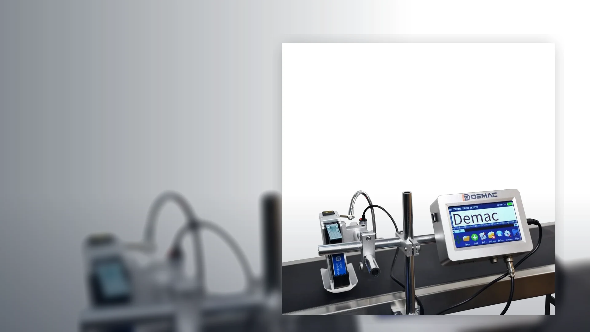
The application footage provides a reference for discussing the coding position. Commissioning should challenge starts, stops, gaps, speed changes, data faults and inspection failures.

  • Load the correct job and confirm the operator can identify it.
  • Run normal and maximum speed with real product spacing.
  • Interrupt each signal or data connection and observe the defined response.
  • Challenge verification and prove the reject, stop or product-hold route.

FAT and SAT challenge tests

Agree the exact tests in the project scope. The list below is a practical starting point, not a claim that every machine includes the named function.

Normal production

Correct job, stable product presentation, all expected data, normal and maximum rate, start/stop and planned changeover.

Controlled faults

Printer not ready, low consumable, blocked sensor, encoder loss, invalid data, lost communications and inspection failure.

Recovery

Safe stop or reject, retained job state, operator warning, product clearance, restart and proof that no unverified packs escape.

Coding integration FAQs

Does every coding machine need an encoder?

No. An encoder is considered when print timing must follow variable product or web speed. A stable constant-speed application may use a sensor and fixed timing, subject to the required position accuracy.

Can the J511 or TTO printers connect to a database?

The J511 information refers to USB database and external real-time data support. The T30/T50 list USB, RS232 and TCP/IP. The actual database or system interface still requires a confirmed protocol and software design.

Who should own the coding message: the PLC, printer or ERP?

The project should name one authoritative source for each field. The choice depends on the production workflow, but ownership and change permissions must be explicit.

What happens if the printer loses its network connection?

The required behaviour should be designed and tested. Possible outcomes include retaining an approved job, stopping, alarming or preventing a new batch from starting until data is restored.

How is a rejected pack tracked from inspection to the reject device?

The controls use timing, distance or product tracking appropriate to the line. The delay, gaps, accumulation and reject confirmation should be tested at maximum speed.

Is coding-line integration the same as complete packaging-line integration?

No. This guide focuses on the coding station. For wider mechanical, controls and line-balance work across fillers, cappers, labellers and conveyors, use Packaging Lines UK.

Prepare an interface schedule

Send the host machine, product path, signals, data fields, inspection requirement and preferred failure response with the coding enquiry.

Discuss integration
Contact us