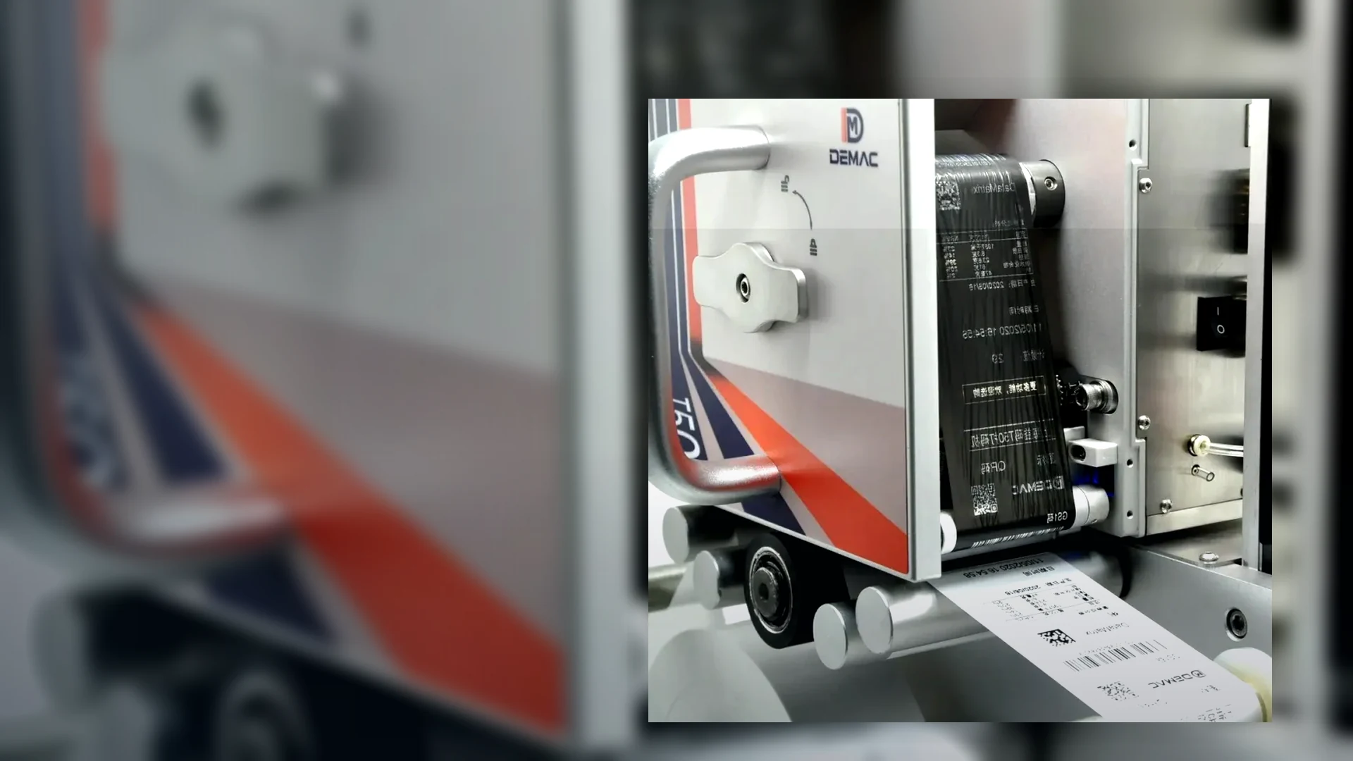
What must be measured before a coder is mounted?
Measure the available envelope, print surface height and movement, product or web path, preferred code area, sensor distance, adjustment range, operator access, guarding, cable routes and nearby equipment that may obstruct maintenance. Include the full range of pack sizes rather than one nominal format.
Photographs and a dimensioned sketch should show stable machine references, not only floor dimensions. A short video of starts, stops and changeovers helps reveal product movement that a static layout misses.
How rigid does the printhead mounting need to be?
The mounting must keep the printhead within the approved distance and angle while the line vibrates, accelerates and is adjusted. Even small movement can alter TIJ throw distance, hot-foil contact or TTO registration, so rigidity should be judged from the code-position and quality tolerance rather than from appearance alone.
Use bracing and stable machine references where possible. Do not rely on a long unsupported arm simply because it can reach the print point.
How should adjustment and changeover be designed?
Adjustment should be repeatable, limited to the movements genuinely needed and referenced with scales, stops, recipes or documented settings. Operators need enough freedom to accommodate the approved formats without being able to move the printhead into an unsafe or unqualified position.
Record the height, lateral position, angle, print gap and sensor delay for each format. The multi-SKU changeover guide connects these physical settings to the correct message and consumable.
Where should sensors, encoders and cables be routed?
Sensors should detect the product or registration feature before the print event with enough controlled distance for the selected printer and line logic. Encoders should reflect the motion that actually governs print position. Cables, air lines where used and network connections should be protected from product contact, washdown, sharp bends, moving parts and changeover damage.
Allow identification and service loops without creating snag points. The final route should remain accessible for fault finding while preserving guarding and hygiene requirements.
How can guarding and consumable access be preserved?
The coding installation should preserve the host machine safety concept and provide safe access for ribbon, cartridge or type changes, cleaning and inspection. The printhead should not be positioned where routine work requires reaching through a dangerous movement or removing guards without the approved isolation procedure.
Confirm how doors, interlocks, covers and extraction or washdown arrangements interact with the coder. A site-specific machinery risk assessment remains necessary for the final installation.
What should be checked during installation and SAT?
Check the bracket and fasteners, adjustment references, print gap, product presentation, sensor and encoder signals, cable protection, guarding, consumable access and the complete code at every approved format. Run normal speed, changes of speed, gaps, stops and restarts to confirm that the physical relationship remains stable.
Retain the final layout, photographs and format settings with the accepted application record so later maintenance does not return the printer to an unqualified position.